 |
| Raspberry Pi – Model B |
The heart of Raspberry Pi is Broadcom BCM2835 media processor includes following features.
- ARM1176JZF-S CPU Core : ARM11 ARM architecture v6 and is clocked at 700MHz (The firmware includes options for various Turbo Modes, through which user can overclock the device up to 1GHz without affecting the warranty).
- Broadcom VideoCore IV GPU
- DSP Core
- Started with 256MB of RAM and then upgraded to 512MB
The LAN Controller LAN9512 provides 10/100MB Ethernet and 2xUSB2.0. This is not present in Model A, hence it contains only one USB which is provided by the BCM2835.
 |
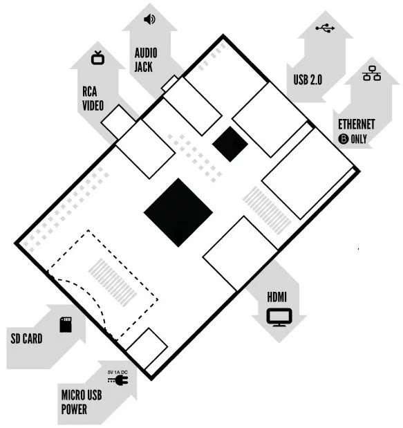
| Different Connectors of Raspberry Pi |
Raspberry Pi uses Linux Kernel based operating systems. Raspberry Pi Foundation recommends the OS Raspbian, which is a Debian based operating system optimized for Raspberry Pi. The large black square in the above diagram shows Broadcom BCM2835 and small black square is the LAN Controller LAN9512.
Expansion Headers in Raspberry Pi
The device contains 26 pin (2×13) header (P1) for interfacing external devices having following features.
- Eight GPIO pins at 3v3
- Two Pins for UART (Universal Asynchronous Receiver Transmitter) which is 3v3 TTL compatible or it may be used as GPIO pins.
- Five Pins for SPI (Serial Peripheral Interface) 3v3 or it may be used as GPIO pins.
- Two Pins for I2C (Inter-Integrated Circuit) 3v3 or it may be used as GPIO pins.
- Nine Pins for Supply : two 3v3, two 5v and five GND
The device also contains 8 pin and 7 pin headers (P2 and P3) for providing GPU JTAG and LAN9512 JTAG respectively. These headers are not fitted in latest boards but pads are provided for soldering. JTAG stands for Joint Test Action Group and is used for IC debugging.
Another 8 pin header (2×4) expansion (P5) is provided on the bottom of the board (not fitted, pads are provided) having following features.
- Four GPIO pins at 3v3
- Three Supply pins 3v3, 5v and GND
- Two pins for Second I2C
- I2S (Integrated Interchip Sound) Interface
- Handshake signals for UART described in the header P1
Another 2 pin header (P6) is provided in latest boards (not fitted) to connect hardware reset button. Header P4 is used to connect Ethernet RJ45 Jack provided in the Model B.
5 Status LED’s
- D5 Green LED : SD Card Access, labeled as ‘OK’ in Rev1.0 boards and changed to ‘ACK’ on Rev2.0
- D6 Red LED : 3.3V Power, labeled as ‘PWR’.
- D7 Green LED : LAN Full Duplex, only present in Model B and labeled as ‘FDX’.
- D8 Green LED : LAN Link/Activity, only present in Model B and labeled as ‘LINK’
- D9 Yellow LED : LAN 10/100Mbit, only present in Model B, labeled incorrectly ’10M’ in Rev1.0 boards and then corrected to ‘100’ on Rev2.0


No comments:
Post a Comment